Physics - Grade XII or Standard XII
Chapter 13: Current Electricity
Electric current:
When electric charges are flowing, we get electric current. Electric current is defined as rate of flow of electric charges. Electric current can be computed using the expression given below:
I = Q / t
where I = electric current, Q = electric charge, t = time. SIUnit of electric current is ampere or A. ampere is defined as follows:
1 ampere = 1 coulomb / 1 second OR 1 A = 1 C / 1 s
Electronic current:
The actual electric current flowing through wires is due to flow of electrons which are negatively charged particles. This current is known as electronic current and it flows from negative terminal to positive terminal in a circuit.
Conventional current:
Electric current was discovered much before the discovery of electron. Scientists assumed that electric current is due to flow of tiny positively charged particles which move from positive terminal to negative terminal in a circuit. This current is known as conventional current. While studing current electricity we use conventional currents.
Steady electric current:
If magnitude of electric current is not changing with time then that electric current is called steady electric current. Hereafter, “electric current” and “current” are treated as synonyms.
Click Here to Go To Top of The Page
Kirchhof’s first law or Kirchhof’s current law:
The algebraic sum of electric currents at any junction is always equal to zero. The sign convenction for this law is as follows: The current flowing toward the junction is treated as positive and current flowing away from junction is treated as negative. In terms of formula this law can be written as follows:
∑ I = 0
Kirchhof’s second law or Kirchhof’s voltage law:
In a closed loop of electrical network, the algebraic sum of potential differences for all components plus the algebraic sum of all E.M.F.’s is equal to zero. Sign convention for this law is as follows: (a) If the direction of tracing is same as that of conventional current flow then potential difference across the resistances is considere negative otherwise it is positive, (b) In terms of formula this law can be written as follows:
∑ IR + ∑ E = 0
where I = electric current, R = resistance, I R = potential difference, E = electromotive force.
Click Here to Go To Top of The Page
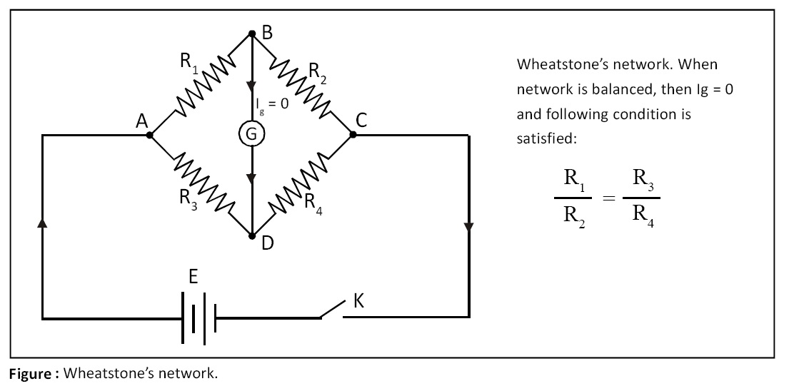
Wheatstone’s network:
It is designed by Charles F. Wheatstone, a British Physicist, for accurate measurement of unknown resistance. It consists of four resistances R1, R2, R3, and R4 which are connected to form a quadrilateral ABCD as shown in the figure. A source of e.m.f. E is connected between diagonally opposite points A and C through key K. A sensitive galvanometer is connected between two other vertices B and D. When network is balanced, no current flows through galvanometer and following condition is satisfied (see figure):
R1 / R2 = R3 / R4
Click Here to Go To Top of The Page
Potentiometer:
A potentiometer is an instrument that is used as a potential divider.
Principle of potentiometer:
The fall of potential per unit length of potentiometer wire is constant, i.e., potential gradient of wire is constant.
Uses of potentiometer:
Uses of potentiometer are as follows:
(a) To measure e.m.f. of a cell,
(b) To compare e.m.f.’s of two cells,
(c) To determine internal resistance of a cell.
Click Here to Go To Top of The Page
Comparison of e.m.f.’s using potentiometer:
Comparison of e.m.f.’s using potentiometer is peroformed as follows:
(a) Direct method. In direct method following formula is used:
E1 / E2 = l1 / l2
(b) Sum and difference method. In sum and difference method following formula is used:
E1 / E2 = [L1 + L2] / [L1 – L2]
where E1 = e.m.f. of first cell, E2 = e.m.f. of second cell, l1 = length corresponding to cell E1, l2 = length of wire corresponding to cell E2, L1 = length of wire corresponding to sum of e.m.f.’s, L2 = length of wire corresponding to difference of e.m.f.’s.
Internal resistance of a cell using potentiometer:
In order to determine the internal resistance of a cell using potentiometer, following formula is used:
r = R (l1 - l2) / l2
where r = resistance of a cell, R = load resistance, l1 = balancing length when no current flows through the cell, l2 = balancing length when current flows through the cell.
Click Here to Go To Top of The Page
Advantages of potentiometer over voltmeter:
Advantanges of potentiometer over voltmeter are as follows:
(a) The voltmeter is used to measure terminal p.d. (potential difference) of cell while potentiometer is used to measure small terminal p.d. as well as e.m.f. (electro motice force) of the cell.
(b) The accuracy of potentiometer can be easily increased by increasing the length of wire.
(c) A small p.d. can be measured accurately with the help of potentiometer. The resistance of volt- meter is high but not infinity to work as an ideal voltmeter.
(d) The internal resistance of a cell can be measured with the help of potentiometer.
Disadvantages of potentiometer:
Disadvantages of potentiometer are as follows:
(a) Voltmeter is a direct reading instrument while a potentiometer is not so.
(b) Votmeter is portable whereas a potentiometer is non-portable.
Click Here to Go To Top of The Page
Wheatstone’s meter bridge:
Wheatstone’s meter bridge is based on Wheatstone’s network and is used to determine unknown resistance. It consists of a thin, uniform conducting wire AC one meter long (hence the name meter bridge), stretched on rectangular wooden board between two thick L shaped metal (copper) strips C1, C2 as shown in the below given figure. The third central metal (copper) strip C3 is fixed on the board such that two gaps with two metal strips are formed as shown in the below given figure. The unknown resistance is connected in one gap and resistance box is connected in another gap. Battery E, key K and rheostat Rh are connected to meter bridge as shown in the below given figure. A suitable value of resistance R is taken in the resistance box and steady current is set round the circuit. By sliding the jockey on wire AC a null point or balance point is obtained for which galvanometer G shows no deflection. The lengths on wire AC – lx and ly – are noted. At null point, following condition is satisfied:
X / R = lx / ly
Therefore,
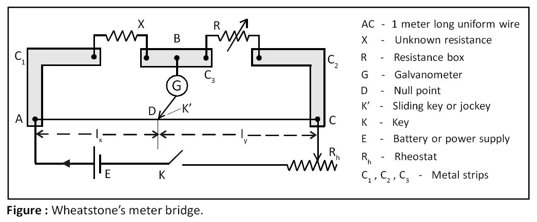
X = R (lx / ly)
Click Here to Go To Top of The Page
Kelvin’s method to determine resistance of galvanometer:
In this method Wheatstone’s meter bridge is used shown in the above given figure with some changes in the circuit. Unknown resistance X is done away with. Galvanometer G fitted across BK' is removed and fitted across the first gap. Kelvin’s method is equal deflection method. Deflection in galvanometer is noted when jockey is not touching the wire. Then point D is found on the wire by sliding the jockey on wire for which galvanometer shows same deflection. For this condition, we have:
r / R = lx / ly
Therefore,
r = R (lx / ly)
where r = resistance of galvanometer.
Click Here to Go To Top of The Page