Physics - Grade XII or Standard XII
Chapter 14: Magnetic Effects of Electric Current
Magnetic effect of electric current:
Danish scientist Oersted in 1820 discovered that when an electric current is sent through a conductor, magnetic field is produced around the conductor. The phenomenon in which an electric current flowing through a conductor produces magnetic field around it is called magnetic effect of an electric current.
Force on charge due to electric field:
Force on charge due to electric field is given by the following expression (bold letters indicated vector quantities):
F = q E
where F = electric force on charge, q = magnitude of charge, E = electric field intensity.
Force on moving charge due to magnetic field:
Force on moving charge due to magnetic field is given by the following expression (vector quantities are shown in bold):
F = q (v × B)
where F = magnetic force on moving charge, q = magnitude of charge, v = velocity, B = magnetic flux density. F, v, and B are vector quantities and hence shown in bold. There is cross product of v and B in parentheses and magnitude of this cross product is v B sin θ where θ is angle between v and B.
Click Here to Go To Top of The Page
Force on moving charge due to electromagnetic fields (Lorentz force):
Force on moving charge due to electro- magnetic fields is given by the following expression (this is known as Lorentz force expression):
F = q (E + v × B)
where F = magnetic force on moving charge, q = magnitude of charge, v = velocity, B = magnetic flux density. F, E, v, and B are vector quantities and hence shown in bold. There is cross product of v and B and magnitude of this cross product is v B sin θ where θ is angle between v and B.
Force on current carrying conductor in magnetic field:
Force on current carrying conductor in magnetic field is given by the following expression:
F = I (l × B)
where F = force on current carrying conductor in magnetic field, I = current flowing through conductor, l = length of conductor, B = magnetic flux density. F, l, and B are vector quantities and hence shown in bold. There is cross product of l and B and magnitude of this cross product is l B sin θ where θ is angle between l and B. Direction of l is taken to be same as that of current I. Direction of F can be found conveniently using Fleming's left hand rule.
Click Here to Go To Top of The Page
Fleming’s Left hand rule:
Fleming’s left hand rule is used to find the direction of force acting on a current carrying conductor in magnetic field. Stretch the thumb, fore finger, and middle finger of your left hand mutually perpendicular to each other. Now, if fore finger gives the direction of magnetic field B, and middle finger gives the direction of current I, then thumb gives the direction of force F acting on conductor.
Bar magnet’s poles:
If a bar magnet is suspended freely in air by means of a string then it takes up a position such that one end points to North pole of earth and is called N-pole of bar magnet, and other end points to South pole of earth and is called S-pole of bar magnet.
Right hand thumb rule:
This rule gives us direction of magnetic induction due to electric current flowing through a straight and long conductor. According to this rule, if a current carrying straight conductor is imagined to be held in the right hand such that the thumb points in direction of the current, then curled fingers of the hand indicate the direction of magnetic induction.
Click Here to Go To Top of The Page
Ampere’s law:
Ampere’s law or Ampere’s circuital law states that the line integral of magnetic field of induction B around any closed path in free space is equal to absolute permeability of free space (μ0) times the total current flowing through area bounded by the path. This law can be stated in terms of an equation as follows:
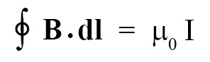
where B = magnetic flux density, dl = small part of loop or closed path, μ0 = permeability of free space = 4π × 10-7 Wb/Am, I = total current flowing through area bounded by the closed path. B and dl are vector quantities hence shown in bold font style. Integrand consists of dot product of B and dl.
Click Here to Go To Top of The Page
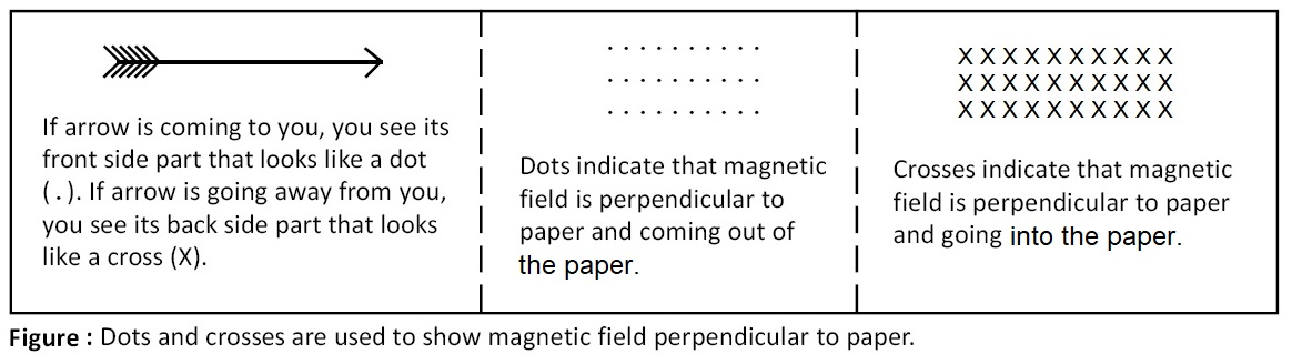
Magnetic field perpendicular to plane of paper:
If magnetic field is perpendicular to plane of paper then it is shown either as dots (•) or crosses (X). Dots means magnetic field is coming out of paper and coming towards you. Crosses means magnetic field going into the paper and going away from you. This convention is developed from arrow. If an arrow is coming towards you, you see its pointed front part that looks like a dot. If arrow is going away from you, you see its backside part that looks like a cross.
Solenoid:
In a solenoid, conducting and insulated wire is wound over a cylindrical surface.
Toroid:
In a toroid, conducting and insulated wire is wound over a doughnut like surface.
Click Here to Go To Top of The Page
Applications of Ampere’s law:
Using Ampere’s law we can determine magnetic flux density due to long straight conductor, long straight solenoid, etc.
(a) Magnetic flux density due to a long straight conductor carrying current is given by:
B = (μ0/4π) × (2I/r)
where B = magnetic induction or magnetic flux density at distance r from conductor, I = current.
(b) Magnetic flux density along the axis of a long straight solenoid, well inside solenoid:
B = μ0 n I
Magnetic flux density along the axis of a long straight solenoid, at the end of solenoid:
B = (1/2) μ0 n I
where B = magnetic flux density along the axis of a long solenoid, I = current through wire, n = number of turns of wire per unit length, μ0 = permeability of free space = 4π × 10-7 Wb/Am.
Click Here to Go To Top of The Page
(c) Magnetic flux density along the axis of toroid:
B = μ0 n I
where B = magnetic flux density along the axis of a toroid, I = current through wire, n = number of turns of wire per unit length, μ0 = permeability of free space = 4π × 10-7 Wb/Am.
Moving coil galvanometer:
Galvanometer is a device with the help of which a very small electric current can be detected. In a moving coil galvanometer, a moving coil is suspended in magnetic field due to a permanent magnet. When current is passed through this coil, it is deflected accordingly. There are two types of moving coil galvanometers: (a) suspended coil type, and (b) pivoted coil type.
Applications of moving coil galvanometer:
Moving coil galvanometer can be used as:
(a) Ammeter,
(b) Voltmeter, and
(c) Ballistic galvanometer.
Click Here to Go To Top of The Page
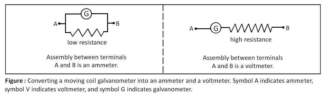
Ammeter:
In order to convert a moving coil galvanometer into an ammeter, we are required to connect a low resistance in parallel with a moving coil galvanometer. This resistance is called a shunt. Ideal ammeter has zero resistance but real ammeter has finite and small resistance.
Voltmeter:
In order to convert a moving coil galvanometer into a voltmeter, we are required to connect a high resistance in series with a moving coil galvanometer. Ideal voltmeter has infinite resistance but a real voltmeter has very high but finite resistance.
Cyclotron:
Cyclotron is a circular particle accelerator, which utilizes a magnetic field to bend charged particles into a circular path and electric field to accelerate them to high velocities.
Click Here to Go To Top of The Page
Principle of cyclotron:
When a charged particle (preferably positive) moves with a definite periodic time, again and again, perpendicular to uniform magnetic field and is accelerated repeatedly by high frequency electric field, traces a spiral path of increasing radius. In this way, the positively charged particle is accelerated to high speed and gains sufficient, large amount of energy.
Construction of cyclotron:
Cyclotron consists of two D shaped semicircular hollow metal boxes, which are called ‘dees’ and generally denoted by D1 and D2. There is a small gap between the two dees. The two dees are kept in the space between two pole pieces of huge electromagnet; which is capable of producing magnetic field of the order of 15,000 gauss, perpendicular to the plane of dees. An alternating potential of the order of 10,000 volt and frequency 107 Hz is applied between the dees. Electric field causes the energy to increase. Under the influence of magnetic field, charged particles traverse circular path. The dees D1 and D2 are enclosed in cylindrical evacuated chamber C. The evacuated chamber along with dees D1 and D2 is placed between the poles of strong magnet. Positive ions are produced in the gap between the two dees by ionization of gas.
Click Here to Go To Top of The Page
Working of cyclotron:
The positive (or negative) ions produced at the centre of gap between D1 and D2 are connected to high frequency alternating potential, its polarities are periodically reversed. If D1 is at positive potential then D2 is at negative potential, therefore positive ions in D1 are repelled from D1 and get attracted to D2. Magnetic field that is perpendicular to dees ensure that ions traverse a circular path, but because of increasing velocity this path is actually a spiral one. Frequency of alternating potential is chosen so that as soon as ions arrive in D2 the polarities of D1 and D2 are reversed. Once again ions in D2 are repelled from D2 and get attracted to D1. As velocity of ions is increasing, ions traverse spiral path. When radius of circular path becomes equal to radius of dee then ions emerge from dee with large velocity and are used for various applications.
Click Here to Go To Top of The Page
Important equations related to cyclotron:
Important equations related to cyclotron are as follows:
(a) Magnetic resonance frequency:
f = q B / (2 π m)
(b) radius of Dee:
R = m v/ (B q)
(c) Linear speed of ion when it exits the cyclotron:
v = B q R / m
(d) Time period of rotation of ion:
T = 2 π m / (B q)
(e) Angular frequency of ion (ω):
ω = B q / m
(f) Kinetic energy of ion when it exits the cyclotron (KE):
KE = (q B R)2 / (2 m)
where f = magnetic resonance frequency = frequency of rotation of ion = frequency of applied AC voltage, q = charge on ion, B = magnetic flux density, R = radius of the dee, m = mass of ion, T = time period of rotation of ion, ω = angular frequency of ion.
Click Here to Go To Top of The Page