Physics - Grade XII or Standard XII
Chapter 16: Electromagnetic Induction
Induced current and induced e.m.f.:
In 1831, Michael Faraday and Joseph Henry independently discovered that when there is relative motion between coil of conducting wire and magnet then electric current is produced in a coil. The current produced is called induced current and the corresponding e.m.f. is called induced e.m.f. E.m.f. stands for electro motive force.
Electromagnetic induction:
The phenomenon of producing an induced e.m.f. in a conductor or conducting coil due to changing magnetic flux or field is called electromagnetic induction.
Faraday’s first law:
Whenever there is change in the magnetic flux associated with a coil, an e.m.f. is induced in the coil.
Faraday’s second law:
The magnitude of induced e.m.f. is directly proportional to the rate of change of magnetic flux through the coil. This law can be expressed as (this is not a finished law, in finished law there is negative sign associated with R.H.S.):
e = dφ/dt
where e = induced e.m.f., dφ = change in magnetic flux through coil in time dt.
Click Here to Go To Top of The Page
Lenz’s law:
The direction of induced e.m.f. or current in the conducting coil or conductor is such as to oppose the change in magnetic flux which produced it. This law can be expressed as follows (notice the negative sign prefixed to R.H.S. which is due to Lenz’s law):
e = –dφ/dt
where e = induced e.m.f., dφ = change in magnetic flux through coil in time dt.
Fleming’s right hand rule:
Stretch the thumb, fore finger, and middle finger of right hand mutually perpendicular to each other. Now, if fore finger represents the direction of magnetic field, and thumb represents the direction of motion of the conductor, then the middle finger represents the direction of induced e.m.f. or current in the conductor.
Eddy currents:
Every metal consists of large number of free electrons which move randomly within the metal. When piece of metal is subjected to a changing magnetic flux, the electrons expe- rience forces and move in circular paths of different radii depending upon their speeds. These circular paths of electrons produce currents which resemble eddies or whirlpool in liquid hence these currents are called eddy currents.
Click Here to Go To Top of The Page
Applications of eddy currents:
Applications of eddy currents are as follows:
(a)
Dead beat galvanometer:
In dead beat galvanometer, eddy currents are used to bring the oscillating coil quickly to rest.
(b)
Induction furnace:
In induction furnace, eddy currents are set up in a piece of metal to heat and melt it.
(c)
Electric brakes:
To stop the train, the driver cuts off an electric power supplied to the motor. At the same time a magnetic field is applied to a rotating drum fixed to the axle. The strong eddy currents in the rotating drum oppose the motion and the train stops almost instantaneously.
(d)
Speedometer:
Speedometer consists of a rotating magnet that is rotating according to speed of vehicle. Magnet rotates in aluminium drum, eddy currents are produced in the drum, and the drum turns in the direction of the rotating magnet. A pointer attached to the drum indicates the speed of the vehicle on a calibrated scale.
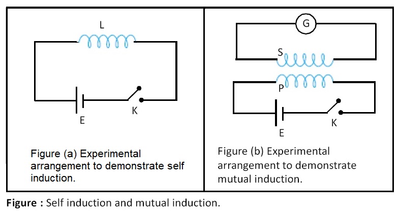
Self induction:
The phenomenon of production of an induced e.m.f. in a coil, due to change in current in the same coil is called as self induction. See figure.
Click Here to Go To Top of The Page
Coefficient of self induction or self inductance (L):
Coefficient of self induction or self induc- tance ‘L’ is defined as the ratio of e.m.f. induced in the coil to the rate of change of current in the same coil. Coefficient of self induction is also called the measure of electrical inertia. It can be expressed as follows:
L = e / (di/dt)
where e = induced e.m.f., di/dt = rate of change of current. L is a scalar quantity. SIU of L is H or henry. H or henry is defined as follows:
1 ohm × 1 second = 1 henry
Inductance coil or inductor:
A coil with self inductance ‘L’ is called inductance coil or inductor. Mutual induction : It is the phenomenon of production of an induced e.m.f. in one coil (P or primary coil) due to change of current in a neighbouring coil (S or secondary coil). See figure.
Click Here to Go To Top of The Page
Coefficient of mutual induction or mutual inductance (M):
Coefficient of mutual induction or mutual inductance ‘M’ of the two coils is defined as the ratio of e.m.f. induced in one coil to the rate of change of current in the other coil.
M = es / (dip/dt)
where es = induced e.m.f. in secondary coil, dip/dt = rate of change of current in primary coil, M = coefficient of mutual induction. M is a scalar quantity. SIU of M is H or henry.
Click Here to Go To Top of The Page
Displacement current:
James Clerk Maxwell modified Ampere’s circuital law as follows:
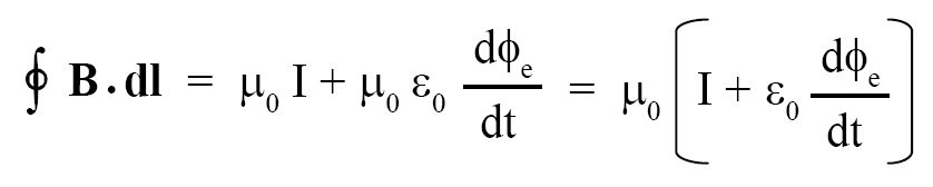
The quantity (ε0 dφe/dt) the above given equation is called “displacement current.” In this equation, B = magnetic flux density, dl = small part of loop or closed path, μ0 = permeability of free space = 4π × 10-7 H/m, I = current flowing through area bounded by the closed path, ε0 = permittvity of free space = 8.85 × 10⁻¹² F/m, φe = electric flux across the loop. The displacement current is different from conduction current, it is produced when electric field or electric flux varies with time.
Transformer:
Transformer is a device that receives electric power at one voltage and delivers at the other voltage provided that electric supply is of alternating current type. Transformer works on the principle of mutual induction. Transformer consists of two coils, called primary (input coil) and secondary (output coil), insulated from each other and wound on a soft iron core.
Click Here to Go To Top of The Page
A.C. electric supply:
A.C. (alternating current) electric supply can be expressed as follows:
e = e0 sin ωt
where e = instantaneous voltage, e0 = peak voltage, ω = angular velocity, t = time. If we plot a graph of a.c. voltage against time then we get sine wave.
Click Here to Go To Top of The Page
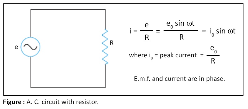
A.C circuit with resistor:
In A.C circuit with resistor R, the current i through circuit is given by the following expression (see figure):
i = i0 sin ωt
where i = instantaneous current, i0 = peak current, ω = angular velocity, t = time, i0 = e0/R, e.m.f. and current are in phase.
Click Here to Go To Top of The Page
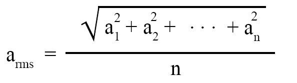
R.M.S. value of a.c. voltage and current:
R.M.S. value means root mean square value. If we take average value of a.c. voltage or current then it will turn out to be zero because positive value in the first half cycle nullifies the negative value in the second half cycle. To circumvent this problem, we are required to take r.m.s. value of voltage or current. R.m.s. value (arms) of ‘n’ numbers a1, a2, ......, an is computed as follows:
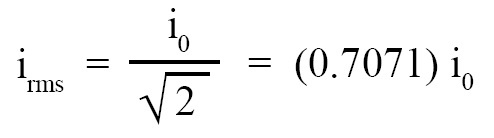
R.m.s. value of alternating current (irms) is given by the following expression (it is derived assuming that alrernating current is sinusoidal, i.e., it varies like a sine curve):
Click Here to Go To Top of The Page
R.m.s. value of a.c. voltage (erms) is given by the following expression (it is derived assuming that a.c. voltage is sinusoidal, i.e., it varies like a sine curve):
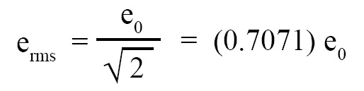
where irms = rms value of alternating current, i0 = peak value of alternating current, erms = rms value of a.c. voltage, e0 = peak value of a.c. voltage.
Click Here to Go To Top of The Page
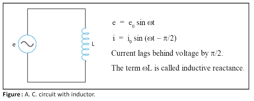
A.C. circuit with inductor:
When a.c. supply is fed to an inductor (figure 16), current and voltage in circuit are given by the following equations:
e = e0 sin ωt
i = i0 sin (ωt – π/2)
Here, (a) current lags behind the voltage by /2, and (b) current and voltage are sinusoidal and are having the same frequency.
Click Here to Go To Top of The Page
Inductive reactance (XL):
In an a.c. circuit with an inductor (see the figure given above), we have equations:
e0 = i0 ωL
erms = irms ωL
The term ωL in the above stated equations is called inductive reactance and is denoted by XL. It is analogous to resistance in ohmic circuit.
XL = ωL = 2πfL
SIU of XL is ohm. XL can be defined as the ratio of rms voltage across the inductor to the rms current passing through it. Also, notice that erms is generally denoted simply by e and irms is generally denoted simply by i.
Click Here to Go To Top of The Page
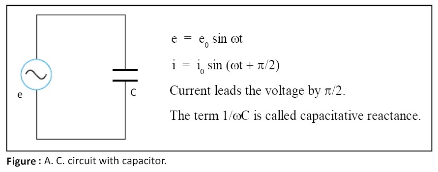
A.C. circuit with capacitor:
When a.c. supply is fed to a capacitor (see the figure given below), current and voltage in circuit are given by the following equations:
e = e0 sin ωt
i = i0 sin (ωt + π/2)
Here, (a) current leads the voltage by π/2, and (b) current and voltage are sinusoidal and are having the same frequency.
Click Here to Go To Top of The Page
Capacitative reactance (XC):
In an a.c. circuit with a capacitor (see the figure given above), we have equations:
e0 = i0 × (1/ωC)
erms = irms × (1/ωC)
The term (1/ωC) in the above stated equations is called capacitative reactance and is denoted by XC. It is analogous to resistance in ohmic circuit.
XC = 1/ωC = 1/(2πfC)
SIU of XC is ohm. XC can be defined as the ratio of rms voltage across the capacitor to the rms current passing through it. Also, notice that erms is generally denoted simply by e and irms is generally denoted simply by i.
Click Here to Go To Top of The Page
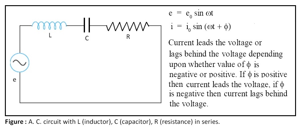
A.c. circuit with L, C, R in series:
When a.c. supply is fed to L (inductor), C (capacitor), and R (resistance) in series, current and voltage in circuit are given by the following equations:
e = e0 sin ωt
i = i0 sin ωt + φ)
where tan φ = (XL – XC) / R
If value of φ is positive then current leads the voltage. When value of φ is negative then current lags behind the voltage. When value of φ is zero then current and voltage are in phase.
Click Here to Go To Top of The Page
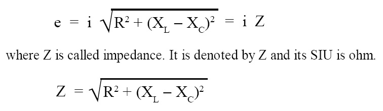
Impedance of AC series LCR circuit (Z):
For LCR series circuit shown in the figure given above, we have the following equation:
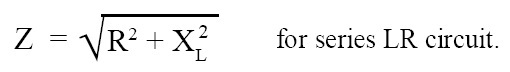
Imedance of AC series LR (or RL) circuit:
If a capacitor is absent in the circuit shown in the above given figure then we get a series LR (or RL) circuit. As capacitor is absent, XC is zero and then impedance Z becomes:
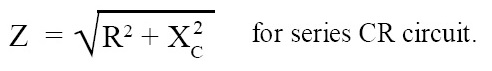
Imedance of AC series CR (or RC) circuit:
If an inductor is absent in the circuit shown in the above given figure then we get a series CR (or RC) circuit. As inductor is absent, XL is zero and then impedance Z becomes:
Click Here to Go To Top of The Page
Power in a.c. circuit with resistor:
If circuit consists of an a.c. source and a resistor (see the figure given above) then power in this circuit is given by the following expression:
Paverage = e × i
where, Paverage is average power for a complete cycle, e = rms voltage, i = rms current through circuit.
Power in LCR series circuit with a.c. supply:
If circuit consists of an a.c. source and L, C, R in series (see the figure given above) then average power in this circuit is given by the following expression:
Paverage = e × i × cos φ
here, Paverage is average power for a complete cycle, e = rms voltage, i = rms current through circuit, cos φ = power factor. Also, tan φ = (XL - XC) / R.
Click Here to Go To Top of The Page
Apparent power and true power:
In the circuit shown in the above given figure for series LCR circuit, we have concepts like apparent power and true power and these are linked by the following expression:
Ptrue average = Papparent average × cos φ
where, Ptrue average = product of e, i, and cos φ, Papparent average = product of e and i, e = rms voltage, i = rms current, cos φ = power factor.
Power factor (cos φ):
The term cos φ is called power factor and its value is equal to R/Z where R is resistance and Z is impedance. Angle φ is called "phase angle." The value of phase angle φ is given by the standard expression:
φ = tan-1 ((XL - XC)/R)
In purely resistive circuit (see the figure given above) φ = 0o and cos φ = 1. In purely inductive and capacitative circuit (i.e., LC circuit) φ = π/2 or 90o and cos φ = 0. When power factor is zero, no power is consumed in such circuit and current in this circuit is called “idle current.”
Click Here to Go To Top of The Page
Resonant LCR circuit:
In series LCR circuit with a.c. supply (see the figure given above), when XC = XL, then resonance occurs and maximum current flows through the circuit. When XC = XL then Z = R, impedance is minimum (for a given value of R) and hence maximum current flows through the circuit.
Resonant frequency (fr):
A given series LCR circuit or parallel LC circuit with a.c. supply can be in resonance only for a particular frequency. The frequency of a.c. for which resonance takes place and maximum current flows through the circuit, is called resonant frequency (fr).
The condition for resonance is XL = XC. But XL = 2πfL and XC = 1/(2πfC). Solving for f, we get:
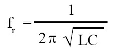
At resonant frequency, maximum current flows through series LCR circuit, whereas minimum current flows through parallel LCR circuit.
Click Here to Go To Top of The Page
Acceptor circuit:
Series LCR circuit accepts current only for resonant frequency and rejects currents of other frequencies and hence it is called acceptor circuit.
Rejector circuit:
Parallel LCR circuit rejects current only for resonant frequency and accepts currents for other frequencies and hence it is called rejector circuit.
Click Here to Go To Top of The Page