Physics - Grade XI or Standard XI
Chapter 9: Ray Optics
Ray of light:
Light follows a straight line path. This path is called a ray of light.
Beam of light:
A bundle of rays of light is called a beam of light.
Pole (P):
The geometrical centre of a spherical mirror is called its pole ( P ).
Principal axis:
The line joining the pole and the centre of curvature of spherical mirror is known as principal axis.
Focal point of concave mirror (F):
When a parallel beam of light is incident on concave mirror (beam is also parallel to principal axis of concave mirror) then the rays in beam are reflected and pass through common point F on the principal axis. This point is called focal point of concave mirror.
Focal point of convex mirror (F):
When a parallel beam of light is incident on convex mirror (beam is also parallel to principal axis of convex mirror) then the rays in beam are reflected and appear to originate from a common point F on the other side of the mirror. This point is called focal point of convex mirror.
Focal length of concave or convex mirror (f):
The distance between focal point and pole of mirror is called as focal length of concave or convex mirror.
Focal plane of concave mirror:
If the parallel beam of light is incident on concave mirror with some angle with principal axis then the reflected rays converge at a point in a plane passing through F and normal to the principal axis. This plance is called focal plane of concave mirror.
Click Here to Go To Top of The Page
Radius of curvature of a spherical mirror (R):
Think of a spherical mirror (i.e., concave or convex mirror) as a portion cut from a spherical shell. The radius of this spherical shell is called radius of curvature of concave or convex mirror (R).
Relation between focal length (f) and radius of curvature (R):
For both the mirrors (concave and convex) the relation between focal length (f) and radius of curvature (R) is given by the following formula:
f = R / 2
Real image:
When light rays entering observer’s eyes actually come from the point where the image is formed, then that image is called as real image. Real image can be photographed.
Virtual image:
When light rays entering observer’s eyes do not actually come from the point where the image is formed, then that image is called as virtual image. Virtual image cannot be photo- graphed.
Cartesian sign convention:
It is based on Cartesian coordinate system, hence the name. According to Cartesian sign convention:
(a) all the ray diagrams are drawn with incident light travelling from left to right,
(b) all the distances are measured from the pole of the mirror or optical centre of the lens (in case of thin lenses),
Click Here to Go To Top of The Page
(c) distances measured to the left of pole of mirror (or optical centre) are regarded as negative and those to the right are regarded as positive,
(d) distances measured above the principal axis are taken positive and those below are taken negative.
Mirror equation:
Mirror equation gives us relation between focal length (f), object distance (u), and image distance (v), as follows:
(1/u) + (1/v) = 1/f
where f = focal length of mirror, u = object distance = distance between object and mirror, v = image distance = distance between image and mirror.
Refraction at single curved surface:
For refraction at a signle surface, the relation between u, v, μ1, μ2, and R is given by the following expression (this relation holds good for real as well as virtual images, and for any pair of refracting media):
(μ2 / v) – (μ1 / u) = (μ2 – μ1) / R
where v = image distance, u = object distance, R = radius of curvature of mirror, μ1 = R.I. of medium 1, μ2 = R.I. of medium 2.
Click Here to Go To Top of The Page
Lens maker’s formula:
Lens maker’s formula or equation is given below:
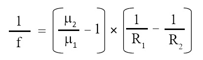
where f = focal length of lens, R1 = radius of one side of lens, R2 = radius of other side of lens, μ2 = R.I. of material of lens, μ1 = R.I. of medium in which lens is placed (e.g., air). Generally, lens is placed in air, and R.I. of air = 1. In this case lens maker’s formula becomes as given below:
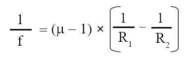
where μ = R.I. of material of lens.
Lens formula:
Lens formula is given below (it is used to compute focal length of a lens):
(1/v) – (1/u) = 1/f
where f = focal length of lens, v = image distance, u = object distance.
Click Here to Go To Top of The Page
Conjugate foci:
The two particular points (say A and B) in the context of a lens are called conjugate foci. If object is placed at point A then image is formed at point B and if object is placed at point B then image is formed at point A.
Combination of thin lenses in contact:
If number of thin lenses are placed in contct with one another, then effective focal length of combination of lenses is given by following expression:
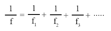
where f = focal length of combination of lenses, f1, f2, f3, ...... = focal lengths of number of thin lenses.
Distance of distinct vision (DDV):
There exists least distance of an object from eye at which the object can be seen clearly without straining eyes. This distance is called distance of distinct vision (DDV). It is about 25 cm for normal human eye.
Simple microscope:
A convex lens is used as simple microscope. Convex lens works as angle magnifier. Microscope is an instrument that is used to see the magnified image of a minute object that is placed close to microscope.
Click Here to Go To Top of The Page
Magnifying power (M.P.) of simple microscope:
The magnifying power of simple microscope is defined as the ratio of the angle subtended at eye by the image to the angle subtended at unaided eye by the object kept at DDV. It is given by the following expression:
M.P. = (D / v) + (D / f)
where M.P. = magnifying power of simple microscope, D = distance of distinct vision, v = image distance, f = focal length of lens.
Compound microscope:
Compound microscope consists of two lenses, namely, objective and eyepiece. The distance between two lenses is called the length L of compound microscope.
Click Here to Go To Top of The Page
Magnifying power of compound microscope:
The magnifying power of compound microscope is defined as the ratio of angle subtended at eye by the final image to the angle subtended at unaided eye by the object placed at DDV (Distance of Distinct Vision). It is given by the following expression :
M.P. of compound microscope = linear magnification of objective × M.P. of eyepiece
M.P. of compound microscope = Mobjective × Meyepiece
M.P. of compound microscope = –(vobjective / uobjective) × (D / ueyepiece)
where v = image distance, u = object distance, D = DDV (Distance of Distinct Vision). Notice that image formed by objective is an object for eyepiece. Negative sign indicates that image is inverted.
Telescope:
Telescope is an instrument that is used to see the distinct objects clearly. A typical telescope consists of two lenses, namely, objective and eyepiece.
Magnifying power (M.P.) of telescope:
Magnifying power of telescope is defined as the ratio of the angle subtended at eye by the final image to the angle subtended at eye by the distant object. It is given by the following expression:
M.P. of telescope = focal length of objective / focal length of eyepiece
Click Here to Go To Top of The Page