Physics - Grade XI or Standard XI
Chapter 12: Magnetic Effects of Electric Current
Electricity and magnetism:
Among electricity and magnetism, electricity is more fundamental than magnetism. Electric current is required to generate a magnetic field. There cannot be a magnetic field without electric current. There can be electricity without magnetism but there cannot be magnetism without electricity. In case of bar magnet, electric currents due to revolving electrons in atoms are responsible for the magnetism.
Oersted’s observation:
Oersted observed that:
(a) electric current generates magnetic field,
(b) direction of magnetic field depends upon the direction of electric current,
(c) direction of magnetic field can be obtained using right hand rule, and
(d) larger the current, stronger the magnetic field.
Click Here to Go To Top of The Page
Magnetic flux density (B):
Magnetic flux density (B) is counterpart of electric field intensity (E). Notice: (a) an electric field can be represented in terms of electric lines of force, similarly, magnetic field can be represented in terms of magnetic lines of force, (b) strength of electric field is given in terms of electric field internsity E, similarly strength of magnetic field is given in terms of magnetic flux density B, (c) at any point in electric field, the magnitude of electric intensity is equal to electric flux per unit area at that point, simiarly, the magnitude of magnetic flux density is equal to the magnetic flux per unit area at that point.
SIUnit of B is weber/metre2 (Wb/m2) or tesla (T). Also, 1 Wb/m2 = 1 T.
tesla (T):
tesla or T is SIUnit of magnetic flux density B. The magnetic flux density is said to be 1 T (T = tesla) if a conductor of length 1 m (m = metre) carrying current of 1 A (A = ampere) experiences a force of 1 N (N = newton) when it is placed with its length perpendicular to the direction of the magnetic field.
Click Here to Go To Top of The Page
Biot-Savart’s law:
According to Biot-Savart’s law, the magnitude of magnetic flux density dB at a point due to a small element of current carrying conductor is : (a) directly proportional to the current, I, (b) directly proportional to the length of the element, dl, (c) directly proportional to the sine of the angle between the element and the line joining the centre of the element to the point, θ, and (d) inversely proportional to the square of the distance of the point from the centre of element, r. Thus we have:
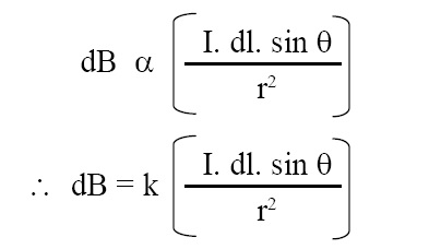
where k = proportionality constant = μ0/(4π) = 10-7 H/m, μ0 = permeability of vacuum or free space.
Magnetic flux density due to an infinitely long and straight conductor:
The magnitude of the magnetic flux density B due to an infinitely long and straight conductor, carrying a current I, at a point at a distance a from the conductor is given by:
B = μ0 I / (2 π a)
where μ0 = permeability of vacuum or free space = 4π × 10-7 H/m.
Click Here to Go To Top of The Page
Right hand rule for direction of B due to electric current I through straight conductor:
This rule gives us direction of magnetic field due to electric current flowing through a straight and long conductor. According to this rule, if a current carrying straight conductor is imagined to be held in the right hand such that the thumb points in direction of the current, then curled fingers of the hand indicate the direction of magnetic field.
Magnetic flux density (B) at the centre of a circular coil carrying current:
Magnetic flux density B at the centre of a circular coil of radius r carrying current I is given by:
B = μ0 I / (2 r)
where μ0 = permeability of vacuum or free space = 4π × 10-7 H/m. If coil is placed in the plane of paper and direction of current is counter-clockwise then magnetic field will be coming out of paper at the centre of coil.
If circular coil has n turns, each of radius r, the magnitude of resultant magnetic flux density at its centre is given by the following expression :
B = μ0 n I / (2 r)
the direction of B in this case also is same as stated above in case of a single turn.
Click Here to Go To Top of The Page
Equivalence between current carrying circular coil and bar magnet:
To a certain limit, there is equivalence between current carrying circular coil and bar magnet. Let a circular loop of wire is in plane of paper and direction of current is counter-clockwise. At the center of loop, magnetic field comes out of the paper. Thus, this loop is equivalent to a bar magnet which is pierced in the paper, perpendicular to plane of paper, so that half part of bar magnet is out of paper and remaining half part is inside the paper. The end of bar magnet that is out of paper is North pole and end that is inside of paper is South pole.
Magnetic flux density at a point along the axis of a coil carrying current:
Magnetic flux density B at a point along the axis of a coil of radius a and turns n carrying current I is given by:
B = μ0 n I a2 / (2 (a2 + x2)3/2)
where μ0 = permeability of vacuum or free space = 4π × 10-7 H/m, n = number of turns in a coil, a = radius of coil, I = current, x = OP, where O is centre of coil and P is a point on the axis of coil at a distance x from O.
Case (i) : Magnetic flux density at the centre of coil. In this case x = 0, and expression reduces to :
B = μ0 n I / (2 r)
Click Here to Go To Top of The Page
Case (ii) : When point P lies far away from the centre of loop. In this case x >> a, and hence, (a2 + x2)3/2 ≈ x3, and expression reduces to:
B = μ0 n I a2 / (2 x3)
Force acting on a conductor carrying current in a magnetic field:
Force F acting on a conductor carrying a current I in a magnetic field is given by the following exprssion:
F = I (L × B)
where B = magnetic flux density, I = current, L = length of conductor, F = force acting on conductor. F, L, and B are vector quantities, I is scalar quantity. As usual, vector quantities are shown in bold. Cross product (aka vector product, aka means also known as) of L and B yields a vector that gives direction of F. The magnitude of force can also be computed from the equation given below:
F = I L B sin θ
where θ = angle between L and B. When conductor is kept parallel to B then θ = 0o and sin θ = 0, and F = 0. When conductor is kept perpendicular to B then θ = 90o and sin θ = 1, and F = I L B. Thus force is maximum when conductor is perpendicular to B and minimum when conductor is parallel to B.
Click Here to Go To Top of The Page
Direction of force acting on a straight current carrying conductor placed in Magnetic Field:
The direction of force F acting on current carrying conductor can be obtained using right hand rule which states: stretch thumb, forefinger and middle finger of your right hand mutually perpendicular. Now if forefinger gives the direction of current I, and middle finger gives the direction of magnetic field B, then thumb gives the direction of force F acting on the conductor. If B is not perpendicular to I then resolve B into two components, one parallel to I and other perpendicular to I. Then use the component of B which is perpendicular to I.
Lorentz force:
The force experienced by a moving charge in electric and magnetic fields is called Lorentz force and it given by the following expression (vector quantities are shown in bold) :
F = q E + q (v × B)
where F = force acting on charge, q = magnitude of charge, E = electric field intensity, v = velocity of charge, B = magnetic flux density. F, E, v, and B are vector quantities, whereas q is a scalar quantity. There is cross product of v and B in parentheses.
Click Here to Go To Top of The Page
Force between two infinitely long current carrying parallel conductors:
Force between two infinitely long current carrying conductors is given by the following expressions:
F = μ0 I1 I2 L / (2 π a)
where F = force between the parallel conductors, μ0 = permeability of vacuum or free space = 4π × 10-7 H/m, I1 = current through one conductor, I2 = current through other conductor, L = length of conductor, a = distance between conductors. When currents I1 and I2 are in the same direction then both conductors attract each other with this force. When the currents I1 and I2 are in the opposite direction then both conductors repel each other with this force. Force per unit length is given by the following expression.
F / L = μ0 I1 I2 / (2 π a)
ampere or A:
A current of 1 ampere (or 1 A) is that current which, when flowing through each of two very long, straight, parallel conductors kept 1 metre apart in free space, produces a force of attraction or repulsion of 2 × 10⁻⁷ N/m on each conductor.
Click Here to Go To Top of The Page
Torque on a current carrying loop placed in magnetic field (τ):
Torque on a current carrying loop placed in a magnetic field is given by the following expressions :
τ = I A B sin θ = M B sin θ
τ = M × B
First expression gives the magnitude of torque and second equation gives torque in vector form. τ = torque on current loop, I = current through loop, A = area of loop, B = magnetic flux density, θ = angle between B and normal to the coil (loop), M = I A = magnetic moment of the current carrying loop, if loop consists of n turns of wire then magnetic moment of loop is given by M = n I A.
Click Here to Go To Top of The Page