Physics - Grade XII or Standard XII
Chapter 12: Electrostatics
Eletric flux:
‘Flux’ is a latin word and its meaning is ‘to flow.’ Electric flux is defined as number of electric lines of force passing normally through a given area. Let electric field E is passing through area dA. Then dot product of E and dA gives us electric flux dφ through area dA. The expression for electric flux dφ is given below (bold letters indicate vector quantities):
dφ = E • dA
SIUnit of electric flux is V.m. Electric flux is a scalar quantity. E and dA are vector quantities but their dot product (scalar product) yields a scalar. Direction of area vector dA is perpendicular to area dA. Total electric flux φ passing through area A can be obtained by integrating both sides of above given expression:
φ = ∫ E • dA
Click Here to Go To Top of The Page
Gauss’ law:
Gauss’ law relates the net flux φ of an electric field through a closed surface (a Gaussian surface) to the net charge q that is enclosed by that surface. It can be stated as:
ε0 φ = q
Gauss’ law can also be stated as:
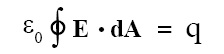
If surface is symmetrical such that E (magnitude of E) is constant on the surface (this is called Gaussian surface) then Gauss’ law simplifies as follows:
ε0 E A = q
where ε0 = permittvity of free space = 8.85 × 10⁻¹² F/m, φ = net electric flux through a closed surface, E = electric field vector, dA = small area vector, E = electric field intensity, A = total area of closed surface, q = charge enclosed in a closed surface.
Click Here to Go To Top of The Page
Gaussian surface:
One of the goals in electrostatics is to find out the electric field at a given point given the charge distribution. We can always find the electric field at any point using the basic formula for E (i.e., electric field E is force per unit charge). However, if charge distribution is symmetrical then we can use Gauss’ law and quickly find out electric field at a desired point. In order to use Gauss’ law, we need to consider an imaginary closed surface, called Gaussian surface, that encloses the given charge distribution. This Gaussian surface need to have the shape that mimics the symmetry of the charge distribution so that electric field can be computed quickly. The point at which the electric field is to be computed should lie on the Gaussian surface.
Examples of Usage of Gaussian Surface:
Examples of usage of Gaussian surface are as follows:
(a) Electric field intensity is to be computed at a point outside a charged conducting sphere. As charge distribution is spherical, the Gaussian surface in this case should be spherical enclosing the sphere and concentric with sphere.
(b) Electric field intensity is to be computed at a point outside an infinitely long charged conducting cylinder. In this case the Gaussian surface is coaxial cylinder that encloses this conducting cylinder.
(c) Electric field intensity is to be computed at a point due to uniformly charged infinite plane sheet. In this case the Gaussian surface is a cylinder with its axis perpendicular to the plane sheet.
(d) Electric field intensity is to be computed at a point near and outside the surface of a charged conductor of any shape. In this case Gaussian surface is nothing but a “Gaussian pillbox” which is nothing but a tiny cylinder with its axis perpendicular to surface of conductor. This tiny cylinder is imagined such that its one half part lies in the conductor and remaining one half part lies outside the cylinder.
Click Here to Go To Top of The Page
Electric field intensity due to charged conducting sphere or shell using Gauss’ law:
Let ‘q’ be total charge on conducting sphere or shell or radius R. Whether we take sphere or shell, charge resides only on its surface. Let the centre of sphere or shell coincides with the origin of coordinate system. Let the point P at which the electric field intensity is to be computed is situated at distance ‘r’ from origin and r > R. Let r be radius vector from O to P. Imagine a spherical surface of radius ‘r’ with its centre at origin; this is our Gaussian surface. Gauss’ law states that:
ε0 E A = q
Putting A = area of Gaussian surface = 4 π r2 we get:
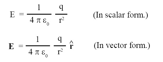
where where ε0 = permittvity of free space = 8.85 × 10⁻¹² F/m and ^r = unit vector along r.
Click Here to Go To Top of The Page
Electric field intensity due to infinitely long charged conducting cylinder or wire using Gauss’ law:
Let ‘λ’ be charge per unit length on charged cylinder or wire. Let ‘R’ be radius of charged cylinder or wire. Let the point P at which the electric field intensity is to be computed is situated at distance ‘r’ from the axis of cylinder or wire and r > R. Imagine a cylindrical surface of radius ‘r’ coaxial with charged cylinder or wire and length ‘l’(it is small el and not one); this is our Gaussian surface. Gauss’ law states that:
ε0 E A = q
Putting A = area of Gaussian surface = 2 π r l and q = λ l, we get:
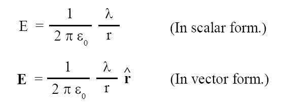
where where ε0 = permittvity of free space = 8.85 × 10⁻¹² F/m and ^r = unit vector along r.
Click Here to Go To Top of The Page
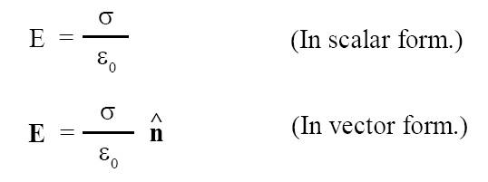
Electric field intensity due to uniformly charged infinite plane sheet using Gauss’ law:
Let ‘σ’ be charge per unit area on charged infinite plane sheet. Imagine a cylindrical surface (this is our Gaussian surface) of cross sectional area (i.e., area of face) ‘S’ and length ‘2r’, perpendicular to plane sheet and situated such that its one half part lies on one side of plane and remaining one half part lies on other side of plane. The charge enclosed in this cylinder is ‘σ S’. The flux coming out through this cylinder actually comes out through faces only. Let the point P at which we want to compute the electric field intensity is at the distance ‘r’ from plane sheet and it is on one of the faces of Gaussian cylinder. Gauss’ law states that:
ε0 E A = q
Putting A = area of Gaussian surface = 2 S and q = σ S, we get:
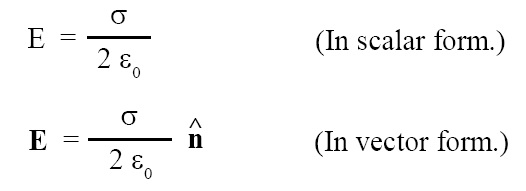
where where ε0 = permittvity of free space = 8.85 × 10⁻¹² F/m and ^n = unit vector along r.
Click Here to Go To Top of The Page
Electric field intensity just outside the surface of charged conductor of any shape using Gauss’ law:
We need to consider a “Gaussian pillbox” (a tiny cylinder) as a Gaussian surface to compute the electric field intensity at the point which is just outside the surface of charged conductor. One half of this pill box lies inside the surface and remaining one half of this pill box lies outside the surface. The flux will come out only through the external face. Let dS be area on the surface and it is equal to area of face of the pillbox. Using the procedure as in preceding cases, we find the following results:
where where ε0 = permittvity of free space = 8.85 × 10⁻¹² F/m and ^n = unit vector along r.
Click Here to Go To Top of The Page
Mechanical force acting on unit area of a charged conductor:
Mechanical force acting on unit area of a charged conductor is given by the following expression:
f = (1/2) ε E2
where f = mechanical force acting on unit area of a charged conductor, ε = permittivity of medium in which conductor is placed, E = electric field at a point just outside the charged conductor.
Energy density of a medium:
During process of charging a conductor, work has to be done to bring charge on the surface of conductor. This work done is stored in the electric field surrounding the conductor in the form of electrostatic energy. The electrostatic energy per unit volume is called energy density. It is given by the following expression:
Energy density = (1/2) ε E2
where ε = permittivity of medium in which conductor is placed, E = electric field at a point just outside the charged conductor.
Dielectric:
An insulating material such as mineral oil or plastic is called a dielectric. Examples: Solid dielectrics: ceramics, glasses, plastics, rubber, mica, and asbestose; Liquid dielectrics: mineral oil, silicone oil, and magnesia.
Click Here to Go To Top of The Page
Dielectric constant:
If dielectric material is filled between the plates of a capacitor then capacitance of capacitor increases by the factor of ‘k’ where ‘k’ is called dielectric constant of dielectric material. By definition dielectric constant of vacuum is one and that of air is slightly greater than one.
Polar molecule:
A polar molecule is one in which center of gravity of positive nuclei and revolving electrons do not coincide, and hence polar molecule has a permanent electric dipole moment. Examples: HCl, H2O, and N2O.
Non-polar molecule:
A non-polar molecule is one in which centre of gravity of positive nuclei and revolving electrons coincide, and hence non-polar molecule does not have a permanent electric dipole moment. Examples: H2, O2, and CO2.
Polarised dielectric (non-polar molecules):
If non-polar dielectric material is placed in an external electric field, then the positive and negative charges in non-polar molecules are displaced in opposite directions so that both forces (electric force and restoring force) balance each other. The non-polar molecules thus acquire induced dipole moment. The dielectric is said to be polarized in external electric field. The induced dipole moments of different molecules add up and give rise to net dipole moment in the direction of field.
Click Here to Go To Top of The Page
Polarised dielectric (polar molecules):
In polar dielectric material the tiny electric dipoles are randomly oriented (in the absence of external electric field) due to thermal agitation. Hence total dipole moment of polar dielectric is zero. When polar dielectric material is placed in external electric field, the tiny electric dipoles get aligned in the direction of field. Thus there is net dipole moment in the direction of field.
Linear isotropic dielectric:
Linear isotropic dielectrics are those substances in which induced dipole moment is induced in the direction of field and is proportional to field strength.
Polarization (P):
Polarization is defined as dipole moment per unit volume and is given by the following expression. This relation is true for linear isotropic dielectrics:
P = χe E
where is P = polarization, χe = electric susceptibility, E = external electric field in which dielectric material is placed.
Polarization charges:
When slab of dielectric material is placed in an external electric field, it gets polarised. As a result one side of slab (say, side 1) acquires positive polarity and other side of slab (say, side 2) acquires negative polarity. The charges so obtained on sides 1 and 2 of the slab are called polarisation charges.
Click Here to Go To Top of The Page
Polarization (P) in terms of surface charge:
Polarization is defined as the amount of induced surface charge per unit area appearing at right angles to applied external electric field. Therefore,
P = qp / A = σp
where qp = polarization charges, σp = charge density of polarization charges, A = area of cross section of dielectric. P is a vector quantity and directed from negative induced charges to positive induced charges. Polarization has dimensions of charge per unit area.
Capacitor:
Capacitor is a system consisting of two conductors having equal and opposite charges, +Q and –Q, separated by an insulator (insulating medium) or dielectric. The electric field E in the region between two conductors is proportional to magnitude of electric charge Q. The potential difference V between two conductors is proportional to the magnitude of charge Q.
Click Here to Go To Top of The Page
Capacitance of capacitor:
The ability of capacitor to store electrical potential energy is called its capacitance. The capacitance C of a capacitor is the ratio of magnitude of charge on either of conductors Q to the magnitude of potential difference between two conductors V, as follows:
C = Q / V
The SIUnit of capacitance is farad or F in honor of Michael Faraday.
1 farad = 1 coulomb / 1 volt OR 1 F = 1 C / 1 V
A capacitor has a capacitance of one farad, if the potential difference across it rises by one volt, when one coulomb of charge is given to it.
Parallel plate capacitor:
A parallel plate capacitor consists of two parallel metal plates each of area A separated by a distance d. Space between plates is generally filled with dielectric material. Capacitance of parallel plate capacitor is given by the following expression:
C = A k ε0 / d
where A = area of a plate, k = dielectric constant of dielectric material filled between the plates, d = spacing between the plates, ε0 = permittvity of free space = 8.85 × 10⁻¹² F/m.
Click Here to Go To Top of The Page
Cylindrical capacitor:
Cylindrical capacitor consists of two coaxial cylinders of radius ‘a’ and ‘b’ respectively. The space between cylinders is generally filled with dielectric material.
Spherical capacitor:
Sperical capacitor consists of two thin conentric spherical shells of radii ‘a’ and ‘b’ The space between spherical shells is generally filled with dielectric material.
Effect of dielectric material on capacitance of capacitor:
The effect of dielectric material on capacitance of capacitor is governed by the below given expression:
Cdielectric = k Cair
where Cdielectric = capacitance of capacitor filled with dielectric material, k = dielectric constant of dielectric material, Cair = capacitance of capacitor filled with air.
Energy stored in charged capacitor:
Energy stored in charged capacitor is given by the following expression:
U = (1/2) C V2 = (1/2) Q V
where U = energy stored in charged capacitor, C = capacitance of capacitor, V = potential difference between the plates of capacitor, Q = charge on capacitor.
Click Here to Go To Top of The Page
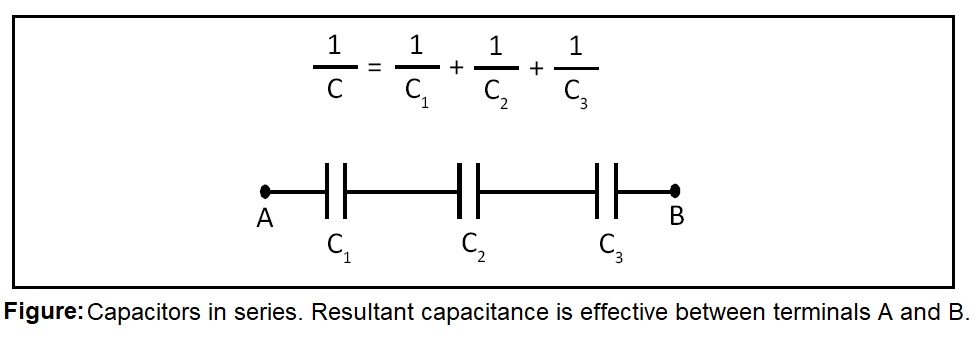
Capacitors in series:
If capacitors are connected in series (see figure) then resultant capacitance of this combination is given by the following expression:
1/C = (1/C1) + (1/C2) + ...... (1/CN)
where C = resultant capacitance of the series combination of capactors 1, 2, ......, N; C1, C2,......, CN = capacitances of capacitors 1, 2,......., N respectively.
Click Here to Go To Top of The Page
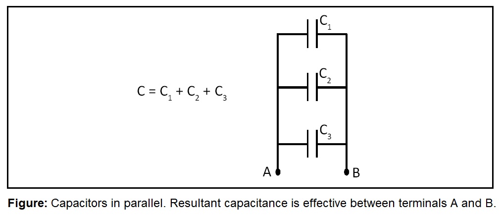
Capacitors in parallel:
If capacitors are connected in parallel (see figure) then resultant capacitance of this combination is given by the following expression:
C = C1 + C2 + ...... + CN
where C = resultant capacitance of the parallel combination of capactors 1, 2, ......, N; C1, C2,......, CN = capacitances of capacitors 1, 2,......., N respectively..
Click Here to Go To Top of The Page
Van de Graff generator:
Van de Graff generator is an electrostatic generator, that can produce high potential of the order of millions of volt. It is used to accelerate charged particles such as protons, deuterons, a-particles. These accelerated charged particles are then used for artificial transmutation. Artificial transmutation is the process in which bombardment of highly energetic particles on nucleus of an element causes it to be transformed into some other element.
Click Here to Go To Top of The Page